What are RTD temperature sensors?
RTDs - or Resistance Temperature Detectors - are temperature sensors that contain a resistor that changes resistance value as its temperature changes. The most popular RTD is the Pt100. They have been used for many years to measure temperature in laboratory and industrial processes, and have developed a reputation for accuracy, repeatability, and stability.
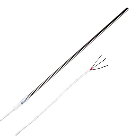
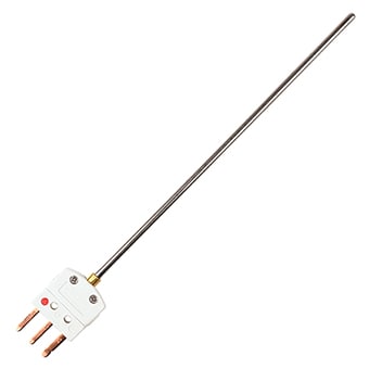
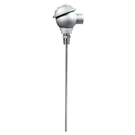
Most RTD elements consist of a length of fine coiled wire wrapped around a ceramic or glass core. The element is usually quite fragile, so it is often placed inside a sheathed probe to protect it. The RTD element is made from a pure material whose resistance at various temperatures has been documented. The material has a predictable change in resistance as the temperature changes; it is this predictable change that is used to determine temperature.
The pt100 is one of the most accurate temperature sensors. Not only does it provide good accuracy, it also provides excellent stability and repeatability. Most OMEGA standard pt100 comply with DIN-IEC Class B. Pt100 are also relatively immune to electrical noise and therefore well suited for temperature measurement in industrial environments, especially around motors, generators and other high voltage equipment.
There are two standards for Pt100 RTDs: the European standard, also known as the DIN or IEC standard, (RTD Temperature vs. Resistance Table) and the American standard (RTD Temperature vs. Resistance Table). The European standard is considered the world-wide standard for platinum RTDs. This standard, DIN/IEC 60751 (or simply IEC751), requires the RTD to have an electrical resistance of 100.00 O at 0°C and a temperature coefficient of resistance (TCR) of 0.00385 O/O/°C between 0 and 100°C.
There are two resistance tolerances specified in DIN/IEC751:
Class A = ±(0.15 + 0.002*t)°C or 100.00 ±0.06 O at 0ºC
Class B = ±(0.3 + 0.005*t)°C or 100.00 ±0.12 O at 0ºC
Two resistance tolerances used in industry are:
1/3 DIN = ±1/3* (0.3 + 0.005*t)°C or 100.00 ±0.10 O at 0ºC
1/10 DIN = ±1 /10* (0.3 + 0.005*t)°C or 100.00 ±0.03 O at 0ºC
Learn more about this formulas here.
The larger the element tolerance, the more the sensor will deviate from a generalized curve, and the more variation there will be from sensor to sensor (interchangeability).
Resistance Temperature Detectors (RTDs) available today can generally be categorized into one of two basic types of RTDs, depending on how their temperature sensing element is constructed. One type of RTD contains thin-film elements and the other type of RTD contains wire-wound elements. Each type is best suited for use in certain environments and applications.
The invention of a resistance thermometer was made possible by the discovery that the conductivity of metals decreases predictably with increases in their temperatures. The first-ever resistance thermometer was assembled from insulated copper wire, a battery and a galvanometer in 1860. However, its inventor, C.W. Siemens, soon discovered that a platinum element yielded more accurate readings at a much wider range of temperatures. Platinum remains the most commonly used material in temperature measurement using RTD sensing elements today.
Learn More
Because every Pt100 element in the circuit containing the sensing element—including the lead wires, connectors and the measuring instrument itself—will introduce additional resistance into the circuit.
How the circuit is configured determines how accurately the sensor’s resistance can be calculated, and how much the temperature reading may be distorted by extraneous resistance in the circuit. Since the lead wire used between the resistance element and the measuring instrument has a resistance itself, we must also supply a means of compensating for this inaccuracy.
There are three types of wire configurations, 2 wire, 3 wire, and 4 wire, that are commonly used in RTD sensing circuits. A 2-wire configuration with a compensating loop is also an option.
Learn More
The RTD PT100, which is the most commonly used RTD sensor, is made of platinum (PT), and its resistance value at 0°C is 100 O. In contrast, a PT1000 sensor, also made of platinum, has a resistance value of 1000 O at 0°C.
The RTD Pt100 and Pt1000 are available in a similar range of tolerances, and both can have similar temperature coefficients, depending on the purity of the platinum used in the sensor. When comparing the Pt100 vs Pt1000 in terms of resistance, keep in mind that resistance value readings for the Pt1000 will be higher by a factor of ten than resistance value readings for the Pt100 at the same temperature. For most applications, the Pt100 and Pt1000 can be used interchangeably depending on the instrument used. In some cases the Pt1000 will work better and be more accurate.
Learn More
The same year that Seebeck made his discovery about thermoelectricity, Sir Humphrey Davy announced that the resistivity of metals showed a marked temperature dependence. Fifty years later, Sir William Siemens proffered the use of platinum as the element in a resistance thermometer. His choice proved most propitious, as platinum is used to this day as the primary element in all high-accuracy resistance thermometers. In fact, the Platinum Resistance Temperature Detector, or RTD Pt100, is used today as an interpolation standard from the oxygen point (-182.96°C) to the antimony point (630.74°C).
Platinum is especially suited to this purpose, as it can withstand high temperatures while maintaining excellent stability. As a noble metal, it shows limited susceptibility to contamination.
The classical resistance temperature detector (RTD) construction using platinum was proposed by C.H. Meyers in 1932. He wound a helical coil of platinum on a crossed mica web and mounted the assembly inside a glass tube. This construction minimized strain on the wire while maximizing resistance.
Meyers RTD Construction Although this construction produces a very stable element, the thermal contact between the platinum and the measured point is quite poor. This results in a slow thermal response time. The fragility of the structure limits its use today primarily to that of a laboratory standard.
Strain-induced resistance changes over time and temperature are thus minimized, and the bird-cage becomes the ultimate laboratory standard. Due to the unsupported structure and subsequent susceptibility to vibration, this configuration is still a bit too fragile for industrial environments.
A more rugged construction technique is a bifilar wound on a glass or ceramic bobbin. The bifilar winding reduces the effective enclosed area of the coil to minimize magnetic pickup and its related noise. Once the wire is wound onto the bobbin, the assembly is then sealed with a coating of molten glass. The sealing process assures that the RTD will maintain its integrity under extreme vibration, but it also limits the expansion of the platinum metal at high temperatures. Unless the coefficients of expansion of the platinum and the bobbin match perfectly, stress will be placed on the wire as the temperature changes, resulting in a strain-induced resistance change. This may result in a permanent change in the resistance of the wire.
There are partially supported versions of the RTD which offer a compromise between the bird-cage approach and the sealed helix. One such approach uses a platinum helix threaded through a ceramic cylinder and affixed via glass-frit. These devices will maintain excellent stability in moderately rugged vibrational applications.
RTD vs Thermocouple or Thermistor
Each type of temperature sensor has a particular set of conditions for which it is best suited. RTDs offer several advantages:
- A wide temperature range (approximately -200 to 850°C)/li>
- Good accuracy (better than thermocouples)/li>
- Good interchangeability/li>
- Long-term stability
With a temperature range up to 850°C, RTDs can be used in all but the highest-temperature industrial processes. When made using metals such as platinum, they are very stable and are not affected by corrosion or oxidation. Other materials such as nickel, copper, and nickel-iron alloy have also been used for RTDs. However, these materials are not commonly used since they have lower temperature capabilities and are not as stable or repeatable as platinum.
Learn More
Both thermistors and resistance temperature detectors (RTDs) are types of resistors with resistance values that vary predictably with changes in their temperature. Most RTDs consist of an element made of a pure metal (platinum is most commonly used) and protected within a probe or sheath or embedded into a ceramic substrate.
Thermistors are made up of composite materials, usually metal oxides such as manganese, nickel or copper, along with binding agents and stabilizers.
In recent years, thermistors have become increasingly popular due to improvements in meters and controllers. Today’s meters are flexible enough to allow users to set up a broad range of thermistors, and to interchange the probes easily.
Learn More


