Mass flow measurement is the basis of many key elements throughout industry, including most recipe formulations, material balance determinations, and billing and custody transfer operations. With these being the most critical flow measurements in a processing plant, the reliability and accuracy of mass flow detection is very important.
A (Brief) History of Mass Flow Measurement
In the past, mass flow was often calculated from the outputs of a volumetric flow meter and a densitometer. Density changes were either directly measured or were calculated using the outputs of process temperature and pressure transmitters. Ultimately, because the relationship between process pressure or temperature and density are not always precisely known, these were not very accurate measurements.
One of the early designs of self-contained mass flow meters operated using angular momentum – it had a motor-driven impeller that imparted angular momentum (rotary motion) by accelerating the fluid to a constant angular velocity. The higher the density, the more angular momentum was required to obtain this angular velocity. Downstream of the driven impeller, a spring-held stationary turbine was exposed to this angular momentum. The resulting torque (spring torsion) was an indication of mass flow. However, with complex mechanical designs and high maintenance costs, these types of meters have been largely replaced by more robust and less maintenance-demanding designs.
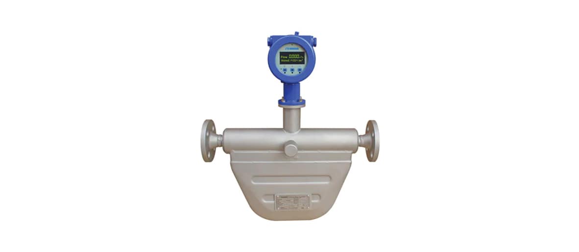
One such design is the Coriolis mass flow meter, which is widely considered the most accurate type of mass flow meter and is widely used in industrial applications for accurate measurement. Coriolis flow meters feature instrumentation that function on the principles of the Coriolis effect – a notable (and strange) phenomenon whereby a mass moving in a rotating system experiences a force acting perpendicular to the direction of motion and to the axis of rotation. The first industrial Coriolis patents date back to the 1950s and the first Coriolis mass flow meters were built in the 1970s.
The Coriolis Principle
It was G.G. Coriolis, a French engineer, who first noted that all bodies moving on the surface of the Earth tend to drift sideways because of the eastward rotation of the planet. In the Northern Hemisphere, the deflection is to the right of the motion; in the Southern Hemisphere, the deflection is to the left. This drift plays a principal role in both the tidal activity of the oceans and the weather of the planet. Because a point on the equator traces out a larger circle per day than a point nearer the poles, a body traveling towards either pole will bear eastward because it retains its higher (eastward) rotational speed as it passes over the more slowly rotating surface of the Earth. This drift is defined as the Coriolis force.
When a fluid is flowing in a pipe and it is subjected to Coriolis acceleration through the mechanical introduction of apparent rotation into the pipe, the amount of deflecting force generated by the Coriolis inertial effect will be a function of the mass flow rate of the fluid. If a pipe is rotated around a point while liquid is flowing through it (toward or away from the center of rotation), that fluid will generate an inertial force (acting on the pipe) that will be at right angles to the direction of the flow.
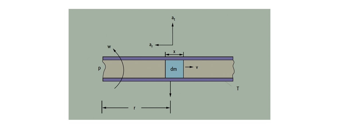 Figure 1: The Coriolis Principle
With reference to Figure 1, a particle (dm) travels at a velocity (V) inside a tube (T). The tube is rotating about a fixed point (P), and the particle is at a distance of one radius (R) from the fixed point. The particle moves with angular velocity (w) under two components of acceleration, a centripetal acceleration directed toward P and a Coriolis acceleration acting at right angle to ar:
ar (centripetal) = w2r
at (Coriolis) = 2wv
In order to impart the Coriolis acceleration (at) to the fluid particle, a force of at (dm) has to be generated by the tube. The fluid particle reacts to this force with an equal and opposite Coriolis force:
Fc = at(dm) = 2wv(dm)
Then, if the process fluid has density (D) and is flowing at constant speed inside a rotating tube of cross-sectional area A, a segment of the tube of length X will experience a Coriolis force of magnitude:
Fc = 2wvDAx
Because the mass flowrate is dm = DvA, the Coriolis force Fc = 2w(dm)x and, finally:
Mass Flow = Fc / (2wx)
This is how measurement of the Coriolis force exerted by the flowing fluid on the rotating tube can provide an indication of mass flowrate. While rotating a tube is not necessarily practical standard operating procedure when building a commercial flow meter, oscillating or vibrating the tube – which is practical – can achieve the same effect.
How Does a Coriolis Flow Meter Work?
Coriolis mass flow meters measure mass through inertia. A liquid or gas flows through a tube which is being vibrated by a small actuator. This artificially introduces a Coriolis acceleration into the flowing stream, which produces a measurable twisting force on the tube resulting in a phase shift. This twisting force is proportional to the mass – and the meter measures mass flow by detecting the resulting angular momentum. Coriolis flow meters are capable of measuring flow through the tube in either the forward or the reverse directions.
In most designs, the tube is anchored at two points and vibrated between these anchors. This configuration can be envisioned as vibrating a spring and mass assembly. Once placed in motion, a spring and mass assembly will vibrate at its resonant frequency, which is a function of the mass of that assembly. This resonant frequency is selected because the smallest driving force is needed to keep the filled tube in constant vibration.
Tube Designs
A tube can be u-shaped or straight form, and some designs can also be self-draining when mounted vertically (Figure 2). When the design consists of two parallel tubes, flow is divided into two streams by a splitter near the meter’s inlet and is recombined at the exit. In the single continuous tube design (or in two tubes joined in series), the flow is not split inside the meter.
In either case, drivers vibrate these measuring tubes. These drivers consist of a coil connected to one tube and a magnet connected to the other. The transmitter applies an alternating current to the coil, which causes the magnet to be attracted and repelled by turns, thereby forcing the tubes towards and away from one another. The sensor can detect the position, velocity, or acceleration of the tubes. If electromagnetic sensors are used, the magnet and coil in the sensors change their relative positions as the tubes vibrate, causing a change in the magnetic field of the coil. Therefore, the sinusoidal voltage output from the coil represents the motion of the tubes.
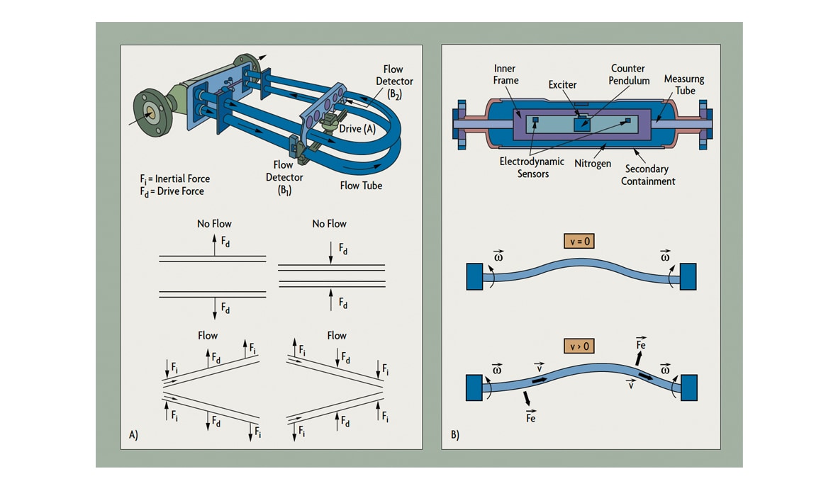 Figure 2-A and Figure 2-B: Two-Tube and Straight-Tube Coriolis Meter Operation
When there is no flow in a two-tube design (Figure 2-A), the vibration caused by the coil and magnet drive results in identical displacements at the two sensing points (B1 and B2). When flow is present, Coriolis forces act to produce a secondary twisting vibration, resulting in a small phase difference in the relative motions. This is detected at the sensing points. The deflection of the tubes caused by the Coriolis force only exists when both axial fluid flow and tube vibration are present. Vibration at zero flow, or flow without vibration, does not produce an output from the meter.
The natural frequency of the tube structure is a function of its geometry, materials of construction, and the mass of the tube assembly (mass of the tube plus the mass of the fluid inside the tube). The mass of the tube is fixed. Since mass of the fluid is its density (D) multiplied by its volume (which is also fixed), the frequency of vibration can be related to the density of the process fluid (D). Therefore, the density of the fluid can be determined by measuring the resonant frequency of oscillation of the tubes. (Note that density can be measured at zero flow, as long as the tubes are filled with fluid and vibrating.)
Wall thickness varies considerably from design to design; however, even the sturdiest tubing will be thinner than the process piping. To obtain the longest meter life it is recommended to select the design with the thickest wall and the slowest flow velocity that can provide the required accuracy and range.
Transmitter Designs
Transmitters can operate on either AC or DC power and require separate wiring for the power supply and for their output signals. The Coriolis flow meter transmitter can be integrally or remotely mounted (Figure 3). The transmitter controls the operation of the driver and processes and transmits the sensor signals. The calibration factor (K) in the transmitter’s memory matches the transmitter to the particular flow tube. This calibration factor defines the constant of proportionality between the Coriolis force and the mass flow rate for the dynamic spring constant of the particular vibrating tubes.
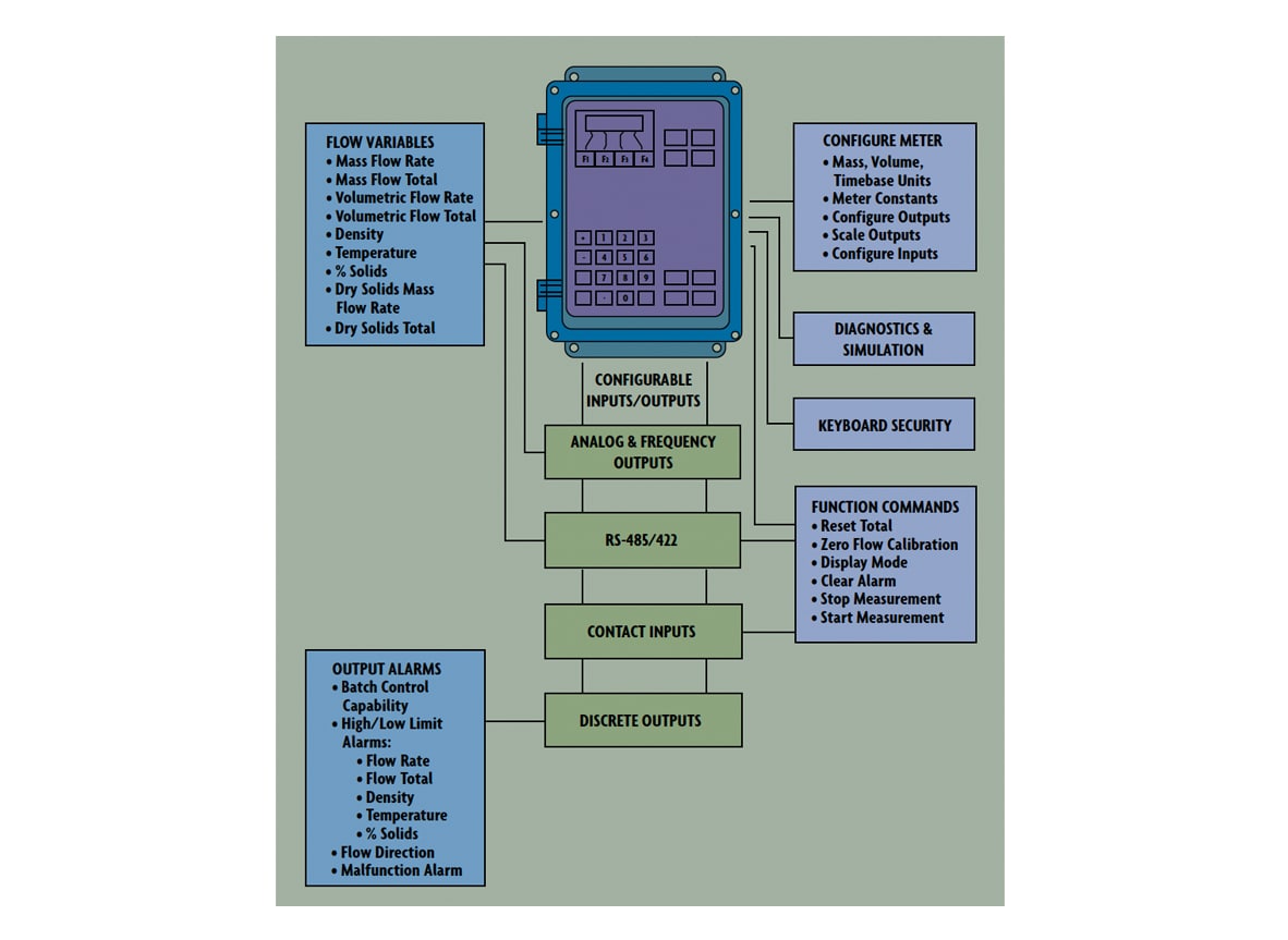 Figure 3: Coriolis Transmitter with Keyboard and Display
The transmitter does more than convert sensor inputs into standardized output signals. Most transmitters also offer multiple outputs, including mass flow rate, total mass flow, density, and temperature. Analog and/or pulse outputs are both available, and intelligent transmitters can generate digital outputs for integration into DCS systems.
Transmitters are often provided with local displays and keypads to allow easy access to process data. Coriolis transmitters provide more than just flow information and ancillary functions. Batch control functions, percent Brix or percent HFCS monitoring, viscosity, percent solids, PID, API gravity, and specific gravity also are available. When viscosity information is desired, the meter pressure drop needs to be measured. Other features may require information to be pre-programmed into the transmitter memory. In addition, transmitters have other hardware and software options, which allow the user to customize them to the application.
Coriolis Evolution
The first generation of Coriolis meters consisted of a single curved, thin-walled tube, in which high fluid velocities were created by reducing the tube cross-sectional area in relation to the process pipe. The tube distortion was measured in reference to a fixed point or plane. The tubes were excited in such a way that localized high amplitude bending forces were created at the anchor points. This resulted in severe vibration problems, which were alleviated by two-tube designs (Figure 2-A).
These two-tube designs reduced external vibration interference, decreased the power needed to vibrate the tubes, and minimized the vibrational energy leaving the tube structure. One driver was used to initiate tube vibration, and two sensors were used to detect the Coriolis deflections. While this design greatly improved performance, the combination of reduced bore, thin-walled tubing, and high fluid velocities (up to 50ft/sec) still resulting in premature meter failure, including potentially catastrophic spills when the meter was used on corrosive and erosive services. In addition, the unrecovered head losses were high (sometimes over 50 psid), and accuracy was not high enough to allow users to convert batch processes into continuous ones.
 Figure 4-A and Figure 4-B: Coriolis Design Improvements
More recent design improvements include the introduction of a variety of new tube shapes, including ones that do not split the flow (Figure 2-B) and the use of multiple drivers (Figure 5A). Thick-walled tubing (five times thicker than early designs), the use of full-bore diameters and heavy manifolds to isolate the tube structure from stresses induced from piping connections, and flow tube housings that double as secondary containment vessels have all contributed to improved performance.
In some designs, torsional stresses replaced bending, to prevent the concentration of stresses that can lead to tube cracking (Figure 5B). In other designs, the effects of pipeline vibration have been minimized by mounting the tube structures transverse to the pipeline.
These improvements increased the number of suppliers and contributed to the development of a new generation of Coriolis meters that are as reliable and rugged as traditional volumetric flow meters. The new designs operate at lower fluid velocities (below 10 ft/sec) and at lower pressure drops (under 12 psid), can be installed in any orientation, and provide longer service life on slurry, viscous, corrosive, or erosive services. The tubes are vibrated well below their endurance limits and typically are made of stainless steel, Hastelloy®, and titanium.
Interferences
The effect of the Coriolis force on the vibrating tube is small. Full-scale flow might cause a deflection of only 0.001 inch. To obtain a flow rangeability of 100:1, sensors must be able to detect deflections to an accuracy of 0.000001 inch in industrial environments where the process pressure, temperature, and fluid density are all changing – and where pipe vibration interferes with measurement.
The elasticity of metal tubes changes with temperature; they become more elastic as they get warmer. To eliminate the corresponding measurement error, the tube temperature is continuously measured by an RTD element and is used to continuously compensate for variations in tube elasticity.
Coriolis mass flow meters usually are calibrated on water because the constants are valid for all other liquids. Calibration for density is usually done by filling tubes with two or more (stagnant) calibration fluids of known densities.
Accuracy & Rangeability
Coriolis meters provide 0.1-2% of rate inaccuracy of a mass flow range of up to 100:1. In general, curved tube designs provide wider rangeability (100:1 to 200:1), while straight-tube meters are limited to 30:1 to 50:1 and their accuracy is lower. Overall meter error is the sum of base inaccuracy and zero-shift error, the error attributable to the irregular output signal generated at zero flow conditions. Zero-shift error becomes the dominant portion of total error at the lower end of the flow range, where the error is between 1% and 2% of rate. Some manufacturers state the overall accuracy as a percentage of rate for the upper portion of the flow range and as a percentage of span for the lower portion, while others state it as a percentage of rate plus a zero-shift error.
When used for density measurement, the typical error range of a Coriolis measurement is 0.002-0.0005 g/cc.
Errors are caused by air or gas pockets in the process fluid. In the case of homogenously dispersed small bubbles, more power is required to vibrate the tubes, whereas, if the gas separates from the liquid, a damping effect on tube vibration (and, consequently, error) develops. Small voids also cause noise because of the sloshing of the process liquid in the tubes. Larger voids will raise the energy required to vibrate the tubes to excessive levels and may cause complete failure.
Because the flow tube is subjected to axial, bending, and torsional forces during meter operation, if process or ambient temperature and pressure fluctuations alter these forces, performance may be affected, and re-zeroing of the meter may be required.
Variations in the density of the process fluid can affect the frequency transfer function of mechanical systems, necessitating the re-zeroing of older designs to protect them from degraded performance. Because of their tube configurations, newer designs are unaffected by density changes over wide ranges of specific gravity variations.
Sizing & Pressure Drop
Because of the wide rangeability of Coriolis flow meters (30:1 to as high as 200:1), the same flow can be measured by two or three different sized flow tubes. By using the smallest possible meter, one will lower the initial cost and reduce coating build-up but will increase erosion/corrosion rates and head loss, increasing pumping and operating costs.
Downsizing (using a meter that is smaller than the pipe) is acceptable when the pipe is oversized, and the process fluid is clean with a low viscosity.
Different Coriolis meters incur different pressure drops, but in general they require more than traditional volumetric meters, which usually operate at less than 10 psid. This higher head loss is due to the reduced tubing diameter and the circuitous path of flow. Besides pumping costs, head loss can be of concern if the meter is installed in a low-pressure system, or if there is a potential for cavitation or flashing, or if the fluid viscosity is very high.
The viscosity of non-Newtonian fluids is a function of their flowing velocity. Dilettante fluids, for example, increase their apparent viscosity (resistance to flow) as their velocity is increased. This apparent viscosity can be drastically higher than their viscosity when stagnant. In order to provide suppliers with data on the flowing viscosity in a particular pipe, head loss per foot of pipe (used in pump sizing calculations) can be used as an approximation.
Applications & Limitations
Coriolis mass flow meters are the most accurate type of flow meter and are used in many different applications in a wide variety of industries as well as in scientific applications – measuring both corrosive and clean gases and liquids. They provide high accuracy in mass flow measurement, density measurement, temperature measurement, and viscosity.
Unlike velocity-based technologies (such as positive displacement flow meters, ultrasonic flow meters, and turbine flow meters), Coriolis mass flow meters can detect the flow of any kind of moderately dense gas or low flow fluid, including crude oil and other kinds of fuels, cleaning agents and other chemicals, vegetable oils and animal fats, toothpaste and alcohol, all types of food products, and non-Newtonian liquids. Self-draining designs are available for sanitary applications that meet clean-in-place requirements.
Most meters are provided with intrinsically safe circuits between the flow tube and the transmitter. Therefore, the amount of driving power that can be delivered to the flow tube is limited.
When fluid is unloaded from tank trucks, drums, or railroad cars, slug flow can occur, making the meter output unpredictable. If a slug-flow recovery feature is provided in the transmitter, it will stop the measurement when slug flow is detected by the excessive drive power drawn or by the drop in process density (reduction in sensor output amplitude).
The amount of air in the process fluid that can be tolerated by a meter varies with the viscosity of the fluid. Liquids with viscosities as high as 300,000 centipoise can be metered with Coriolis meters. Gas content in such highly viscous liquids can be as high as 20% with the small bubbles still remaining homogeneously dispersed. Gas content in low viscosity fluids, like milk, will separate at concentrations as low as 1%.
Average-sized (under 2 in.) Coriolis flow meters provide short pay-back periods on applications where measurement accuracy lowers production costs (bathing, billing) or where multiple measurements (including density, temperature, pressure) are needed. On the other h and, they may not be competitive when used in simple flow measurement applications where volumetric sensors are sufficient and where repeatability is more important than precision. The ability to extract data on total mass charged, solids rate, percent solids, and viscosity from a single instrument does lower the total cost of measurement, improves process control, and provides redundancy for other instruments.
Continuous tube designs are generally preferred for slurry and other multi-phase fluid applications. The total flow is divided by splitters in split-tube designs, and the resulting two streams do not have to be at exactly the same mass flow rate to maintain accuracy (they do, however, need to have the same density). Different densities in the two parallel tubes imbalances the system and create measurement errors. Therefore, if there is a secondary phase in the stream, a simple flow splitter may not evenly distribute the flow between the two tubes.
Continuous tube designs are also preferred for measuring fluids that can coat and/or clog the meter. Continuous tubes, if sized to pass the largest solid particles in the process fluid, are less likely to clog and are easier to clean.
Straight-tube designs can be cleaned by mechanical means, while curved-tube designs are usually washed-out using cleaning solutions at velocities in excess of 10ft/sec. Straight-tube designs also are preferred for sanitary applications due to self-draining requirements.
Long, bent tubes twist more easily than do short, straight tubes and, therefore, will generate stronger signals under the same conditions. In general, u-shaped designs provide wider rangeability (100:1 to 200:1), while straight-tube meters are limited to 30:1 to 50:1 – with lower accuracy.
Straight-tube meters are more immune to pipeline stresses and vibration, are easy to install, require less pressure drop, can be mechanically cleaned, are more compact, and require less room for installation. They are also preferred on services where the process fluid can solidify at ambient temperatures.
Not all meter housings are designed to withstand and contain the pressurized process fluid in case of tube rupture, particularly if the process fluid is likely to vaporize under such conditions. If that is the case, secondary containment housings can be ordered that enclose the entire flow tube, including its housing. Such secondary containment enclosures can be provided with rupture disks or pressure relief valves, and with drains or vents.
